

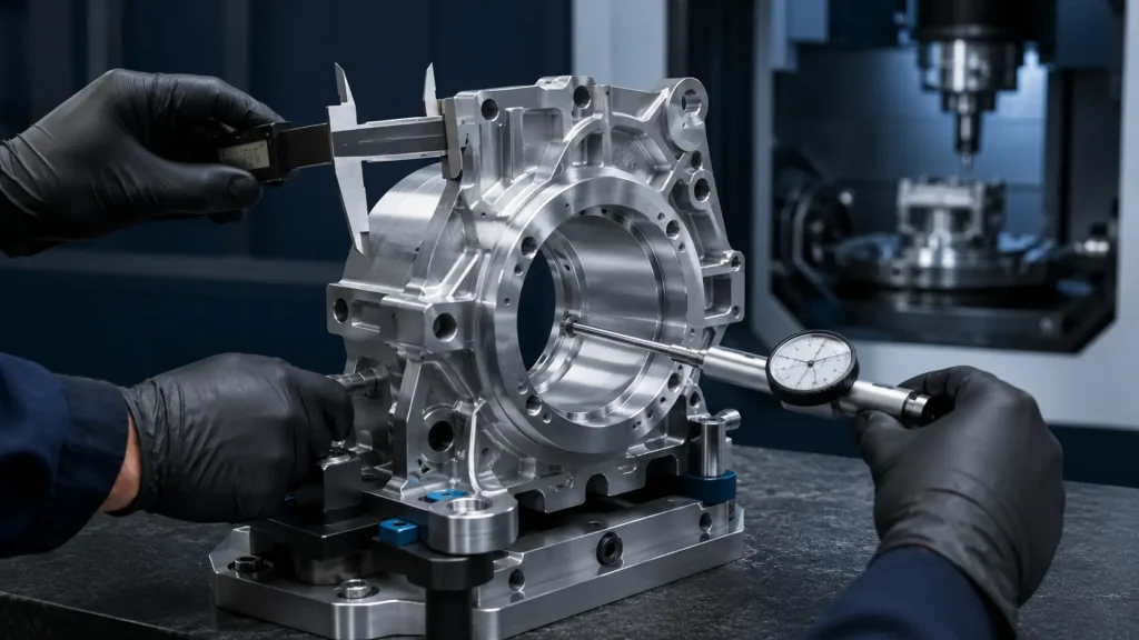
CNC Machining Tolerances: General Tolerances vs Critical Dimensions
A CNC machine may be capable of extremely small movements, but that does not mean every dimension on a part should receive an extremely tight tolerance. The drawing must separate ordinary dimensions from the features that control fit, function, alignment, sealing, motion or safety. Without that distinction, a supplier may quote unnecessary precision, inspect the wrong characteristics or make a technically acceptable part that still fails in assembly.
For buyers sourcing CNC machining services, the most useful question is not simply, ‘What tolerance can the machine hold?’ It is, ‘Which features need which tolerance, relative to what datum, under what material and inspection conditions?’ This article explains how general tolerances and critical dimensions work together to answer that question.
Key takeaway: a critical dimension is defined by functional risk, not only by a small plus/minus value. A broad-looking positional, flatness or runout requirement can be more important than a numerically tighter non-functional size.
General Tolerances and Critical Dimensions: The Difference
| Decision point | General tolerance | Critical dimension |
|---|---|---|
| Purpose | Controls routine, non-individually toleranced dimensions | Protects a defined fit, function, interface or risk |
| Drawing treatment | Applied by a clear title-block or drawing note | Shown explicitly beside the feature or in a feature-control frame |
| Process planning | Usually managed through the normal machining route | May require a dedicated setup, finishing pass, tool, fixture or controlled sequence |
| Inspection | Often sampled with standard gauges, subject to the quality plan | Measured with a defined datum, method, frequency and reporting requirement |
| Cost effect | Provides an economical baseline when it matches process capability | Adds cost only where the functional benefit justifies the control |
What General Tolerances Do - and Do Not Do
A drawing may state a general tolerance such as a company-specific plus/minus rule or a recognised standard and class. That note establishes the default for eligible dimensions without repeating a tolerance next to every value. It can reduce visual clutter, speed quotation and help the manufacturer plan a consistent baseline process.
The note is not a substitute for design intent. It does not automatically control the relationship between two holes, the flatness of a sealing face, the runout of a shaft relative to a bearing journal or the profile of a complex surface. It also does not prove that every machine, material, part size and setup can economically achieve the same limits. Process capability must still be reviewed against the actual geometry, material condition, batch size and inspection method.
General tolerances also require a clear hierarchy. The drawing should state which rule governs, which dimensions are excluded, what units apply and whether individual tolerances override the general note. If the 3D model, PDF drawing, purchase order and supplier standard disagree, the parties should resolve the conflict before production. Nova’s engineering services can support the translation of functional requirements into production-ready data.

A Standards Note: ISO 2768, ISO 22081 and ASME Y14.5
ISO 2768-1:1989 provides general tolerance classes for eligible linear and angular dimensions without individual indications. As of 2026 it remains published but is under revision, so drawings and contracts should identify the exact edition and class rather than saying only ‘standard tolerance.’ The old ISO 2768-2 for general geometrical tolerances has been withdrawn and replaced by ISO 22081:2021.
ISO 1101 defines the symbol language and interpretation rules for geometrical specifications in the ISO GPS system, while ISO 8015 provides fundamental GPS principles. ASME Y14.5 is a widely used alternative framework for dimensioning and GD&T. These systems should not be mixed casually. The drawing should name the governing standard, revision and any company-specific exceptions so designers, machinists and inspectors use the same rules.
What Makes a Dimension Critical?
A feature becomes critical when variation can create a meaningful failure. That failure may be immediate, such as a bearing that cannot be assembled, or gradual, such as uneven wear caused by misalignment. Criticality can also come from a customer interface, a regulatory requirement, service access or an inspection characteristic that must remain traceable across batches.
- Fits and mating sizes: bearing seats, dowel holes, press fits, slip fits, threads, seals and locating bosses.
- Location and orientation: hole patterns, datum faces, perpendicular bores, coaxial journals and assembly interfaces.
- Form and contact: flat sealing faces, straight guide surfaces, round bores and controlled profiles.
- Motion and load transfer: shaft runout, gear centres, bearing alignment and sliding or rotating clearances.
- Safety, performance or compliance: features whose failure affects structural integrity, containment, calibration or certification evidence.
A dimension can be critical without being extremely tight. For example, the position of a four-hole mounting pattern may allow a relatively generous zone but still be critical because all four fasteners must assemble. Conversely, a small decorative step may receive a tight cosmetic tolerance without being function-critical. The drawing should communicate both the limit and the reason behind it through a coherent datum and inspection strategy.
Three Practical CNC Machining Examples
1. Milled Mounting Plate
The overall length, non-mating edge distances and relief-pocket depth may be suitable for the general tolerance. The locating holes and the machined mounting face may be critical because they establish assembly position. Instead of applying a very tight plus/minus value to every coordinate, the designer can establish functional datums and control the hole pattern with an appropriate positional requirement. This gives the CNC milling service a clearer target and gives inspection a repeatable setup.
2. Turned Shaft with a Bearing Seat
The free shaft length or a non-contact chamfer may use the general tolerance. The bearing-seat diameter, shoulder location, surface texture and runout relative to the functional axis are likely to be critical. A controlled CNC turning process can establish the main geometry, while a suitable grinding operation may be selected when final size, form or surface condition requires a dedicated finishing route. The required process should follow the specification, not be assumed from a generic tolerance label.
3. Machined Housing and Sealing Interface
External envelope dimensions may tolerate ordinary variation, but the bore alignment, gasket groove, sealing-face flatness and threaded inserts may determine whether the housing leaks or assembles. Coating or heat treatment can also change critical sizes, so the drawing must state whether a tolerance applies before or after finishing. In an integrated metal manufacturing route, machining allowances and inspection stages should be planned around the final condition of the part.

How Tolerance Choices Affect Cost and Lead Time
| Tolerance decision | Manufacturing effect | Inspection effect |
|---|---|---|
| Blanket tight tolerances | More finishing passes, slower parameters, tighter tool-wear control and higher scrap risk | More characteristics, longer reports and more capable gauges |
| Critical-only tight tolerances | Resources are concentrated on functional features and stable datum setups | Inspection effort follows risk instead of measuring everything equally |
| Multiple setups or distant datums | Additional fixturing and reorientation can introduce stack-up and alignment error | Datum simulation or CMM programming may be required |
| Thin walls, heat treatment or coating | Distortion and material movement may require allowance, sequencing or final machining | Final-state inspection and environmental control become more important |
| Very fine surface requirements | A dedicated finishing process may be needed beyond size control | Profilometry and location-specific reporting may be added |
When GD&T Is Better Than Plus/Minus Tolerancing
A size tolerance controls how large or small a feature may be, but it may not control where that feature is, how it is oriented or how its surface relates to the functional datums. Geometric dimensioning and tolerancing can define those relationships more directly. Position is often useful for hole patterns; flatness for a sealing or mounting surface; perpendicularity for a bore relative to a face; runout for rotating features; and profile for complex surfaces.
GD&T should not be used as decoration. Each datum must represent how the part is located or functions, each control must have a measurable meaning, and the inspection method must be practical. Over-constraining a drawing with redundant controls can create conflicts and cost just as easily as blanket plus/minus tolerances. A short design and manufacturing review is usually cheaper than resolving different interpretations after the first batch has been machined.
From Drawing Review to Inspection Plan
A robust tolerance strategy continues into process control. The manufacturer should review critical features before quotation, select functional datums, plan how much of the geometry can be completed in one setup and identify any feature affected by heat treatment, stress relief or coating. Tool access, workholding force, temperature and material stability can all influence the result.
- First article: confirm the released revision, material, production route and critical characteristics before routine output.
- In-process control: measure features early enough to correct tool wear or drift before value has been added to a nonconforming part.
- Final inspection: verify the agreed characteristics in the condition in which the part will be accepted, including finishing when relevant.
- Sampling and traceability: set frequency by risk, process stability, volume and customer requirements rather than using one universal rule.
- Measurement method: match micrometers, bore gauges, height gauges, CMMs, surface instruments or functional gauges to the characteristic and datum scheme.
Measurement uncertainty matters most near a specification limit. ISO 14253-1 provides decision rules that account for uncertainty when verifying conformity or nonconformity. The buyer and supplier should therefore agree how borderline results will be handled, especially for high-risk features. Nova describes project-specific Inspection and Test Plans, dimensional reporting and CMM use within its quality approach. The exact equipment, sampling level and report format should still be confirmed for each RFQ.

CNC Machining Tolerance RFQ Checklist
Send enough information for the manufacturer to quote the actual control plan rather than assume one. A useful RFQ package includes:
- a controlled PDF drawing and native 3D model with matching part number and revision;
- units, material grade, temper or heat-treatment condition, and any stress-relief requirement;
- the governing general tolerance standard, exact edition and class, plus explicit size and GD&T controls for critical relationships;
- fits, threads, inserts, edge conditions, surface texture and the condition before or after coating;
- a clearly identified list of critical or key characteristics without relying only on colour or informal markup;
- first-article, sampling or 100 percent inspection requirements and the measurements that must appear in the report;
- the required measuring method, functional gauge or customer correlation method where results are method-sensitive;
- prototype and annual volumes, batch size, delivery schedule and expected process changes between prototype and production;
- assembly context, mating-part data and operating information such as load, speed, temperature, sealing or alignment risk.
Frequently Asked Questions
What is a general CNC machining tolerance?
It is a default tolerance applied to eligible dimensions that do not show an individual limit. It must be defined by the drawing, contract or referenced standard; it is not a universal value automatically supplied by every CNC machine shop.
Is a critical dimension always the tightest dimension?
No. Criticality describes the consequence of variation. A moderately sized position zone on a mounting pattern can be more important than a very small tolerance on a non-functional detail.
Should every dimension be individually toleranced?
Usually not. A clear general tolerance can cover routine features, while individual size, fit, GD&T and surface requirements identify the characteristics that need different control. The drawing must remain complete and unambiguous.
How tight can CNC machining tolerances be?
There is no single answer. Achievable and economical tolerance depends on feature type, size, material, geometry, wall thickness, machine and fixture, number of setups, thermal conditions, finishing route, batch size and inspection capability. Feasibility should be confirmed against the specific drawing rather than a marketing number.
Do tight tolerances always require 100 percent inspection?
No. Inspection frequency should follow functional risk, process capability, volume and customer or regulatory requirements. Stable processes may support sampling, while some safety-critical or assembly-critical features may justify full verification.