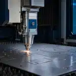


Most of the manufacturing cost in a sheet metal part is decided before a supplier receives the RFQ. Material choice, bend geometry, hole placement, tolerance strategy and assembly design determine how many operations, setups, tools and inspections the part will require. A CAD model may be geometrically valid yet still create avoidable scrap, slow quoting or force the manufacturer to redesign the part before production.
Design for Manufacturing (DFM) aligns functional intent with the realities of cutting, forming, joining, finishing and inspection. Early collaboration with experienced engineering services can expose these constraints while changes are inexpensive. The 12 rules below provide a practical starting point for lower-cost, faster and more repeatable sheet metal parts.
What Is DFM for Sheet Metal Parts?
Sheet metal DFM is the practice of designing a part so that it can be manufactured reliably with available sheet sizes, cutting processes, press-brake tooling, joining methods and finishing systems. It connects the 3D design to the real manufacturing sequence: source material, create the flat profile, form the bends, install hardware, join components, apply the finish and verify the final geometry.
The objective is not simply to minimize piece price. A strong DFM review also protects lead time, part-to-part repeatability, assembly fit, service life and the quality of the technical quotation. It distinguishes truly critical requirements from convenient CAD defaults and converts ambiguous geometry into manufacturable, inspectable requirements.
Throughout this guide, t means nominal sheet thickness and R means the inside bend radius. Ratios such as R ≈ t are useful review prompts, not universal limits. The approved values must be checked against the actual material, temper, grain direction, bend method, V-opening, punch radius, machine capacity and part geometry.
The 12 Rules at a Glance
Rule | Design decision | Typical cost / lead-time effect |
1 | Specify material early | Avoid substitutions, requoting and late process changes |
2 | Use standard, uniform thickness | Improve stock availability and reduce setups |
3 | Match features to the cutting process | Prevent slow cuts, extra operations and redesign |
4 | Standardize inside bend radii | Reuse tooling and stabilize formed geometry |
5 | Provide workable flange lengths | Avoid special tooling and incomplete bends |
6 | Separate holes from bends | Reduce distortion, elongation and manual correction |
7 | Add bend and corner relief | Prevent tearing and uncontrolled edge deformation |
8 | Account for grain, springback and K-factor | Improve flat-pattern and angle accuracy |
9 | Protect bend sequence and tool access | Reduce handling, collisions and extra setups |
10 | Tolerance only functional features | Limit inspection, fixturing and rework burden |
11 | Consolidate parts and simplify joining | Cut hardware, welding and assembly time |
12 | Design for finishing and inspection | Prevent masking, coating and verification delays |
12 DFM Rules for Sheet Metal Parts
Rule 1: Select the Material Grade, Condition and Thickness Early
Do not leave material as a generic label such as “steel” or “stainless.” Grade, delivery condition, thickness tolerance, surface condition and any certification requirement can change laser parameters, punch performance, achievable bend radius, springback, weldability and finish. They also influence availability: a standard stocked sheet may be sourced quickly, while an uncommon grade or finish can dominate the schedule.
Choose the material from functional requirements—strength, corrosion resistance, temperature, weight and appearance—then confirm that it is compatible with the intended steel fabrication or stainless steel fabrication route. If alternatives are acceptable, list them deliberately rather than allowing an uncontrolled substitution after quoting.
Rule 2: Use Standard, Uniform Sheet Thickness Wherever Possible
A standard thickness usually benefits from better availability, predictable tooling and established cutting and bending data. Using one gauge across related parts can reduce material purchases, setup changes and programming effort. It may also improve nesting opportunities when several components share the same sheet.
Avoid changing thickness only to stiffen a local area. First consider a return flange, rib, bead, hem, formed offset or geometry change. These features can increase section stiffness without adding mass to the entire part. However, a formed stiffener is not automatically free: it must have tool access and enough clearance from bends and edges. Compare the complete route, not only material weight.
Rule 3: Match Feature Geometry to the Cutting Process
The best cutting method depends on material, thickness, feature density, edge requirement, quantity and downstream operations. For flexible profiles and frequent design changes, sheet metal laser cutting can create complex contours without dedicated hard tooling. For repeated holes, louvers, knockouts and other compatible features, punch cutting may combine several operations efficiently.
Very small holes, narrow slots, sharp internal corners and dense perforation patterns may slow the process, distort the sheet or require a different method. Do not assume that every detail visible in CAD can be produced economically. Ask the fabricator to confirm the minimum feature size, edge condition and spacing for the selected material and machine, and use standard tooling when a punched feature is intended.

Rule 4: Use Consistent, Tool-Friendly Inside Bend Radii
A common starting point for ductile materials is an inside radius near one material thickness, but the correct minimum is material- and process-specific. Harder grades, thick plate, bends across unfavorable grain direction and some surface-finished materials may need a larger radius to avoid cracking or unacceptable marking.
Use the same inside radius for bends made with the same material and thickness whenever function permits. Consistent radii allow the manufacturer to reuse punches, dies and bend data instead of changing tools or compensating each bend separately. Nova’s press brake bending team can confirm a preferred radius and V-opening for the actual combination. In air bending, the produced radius is influenced by the die opening and material response; a CAD radius alone does not define the shop-floor result.
Rule 5: Provide Enough Flange Length for the Selected Tooling
A press brake needs enough material to remain supported on the die while the punch forms the bend. If a flange is too short, it can fall into the V-opening, form inaccurately or require narrower—and sometimes special—tooling. As an early review range, suppliers often use minimum-flange relationships from roughly 2.5t + R to 4t, but the real limit comes from the V-opening, bend angle, radius, tooling and machine.
Check long flanges too. A return flange can collide with the punch, ram, backgauge or already formed walls even when its length is easy to bend in isolation. If a short or deep return is essential, share the 3D model early so the supplier can simulate the bend and select staged, gooseneck or other suitable tooling before the quote is finalized.
Rule 6: Keep Holes, Slots and Cutouts Away from Bend Zones
Material stretches and compresses around a bend. A hole or slot placed in that deformation zone can become oval, pull toward the bend or create a visible bulge. The closer the feature is to the bend, the more sensitive the result becomes to thickness, radius, angle and material direction.
Published supplier guidance commonly falls within about 2t to 4t from the bend region or inside corner, depending on how the distance is defined and which process is used. Treat that span as a prompt for review, not a drawing rule. Dimension from a clearly defined bend tangent or formed datum. If the feature must be closer, options include moving it, changing its shape, cutting it after forming or accepting a specifically defined deformation.
Rule 7: Add Bend Relief and Corner Relief Where Material Must Flow
When a bend terminates at an edge or beside an unbent wall, the material needs a controlled place to deform. Without relief, the edge can tear, twist or leave an unpredictable protrusion. At intersecting bends, corner relief can also prevent overlap, pinching and cracking.
Relief width should be compatible with the cutting process and material thickness; relief depth generally needs to extend beyond the bend-influence area. A useful review concept is to reach at least beyond R + t, then add the process margin confirmed by the fabricator. Rounded or obround reliefs can reduce stress concentration compared with sharp-ended slots. Avoid cosmetic “mouse bites” added without a functional reason: relief shape affects appearance, strength and finishing.
Rule 8: Account for Grain Direction, Springback and K-Factor
Rolled sheet is direction-dependent. Bending parallel to the rolling direction can be more crack-sensitive in some materials than bending across it, particularly at small radii. Grain orientation can therefore affect both nesting efficiency and formability. Mark critical bend directions in the technical package when the material or application makes orientation important.
After the press force is removed, elastic recovery changes the angle and sometimes the radius. This springback depends on grade, temper, thickness, bend method and tooling. Flat-pattern length also depends on the neutral-axis location, commonly represented by a K-factor. Do not apply one global K-factor to every material and bend. Use validated shop data or allow the manufacturer to generate the production flat from the approved formed model.

Rule 9: Simplify Bend Sequence and Preserve Tool Access
Every bend changes what the press brake can reach next. Deep channels, tall sidewalls, narrow U-shapes, closed boxes and inward return flanges can trap the part or collide with tooling. A design that contains only standard angles may still need multiple setups, rotations or a non-obvious sequence.
Design the whole sequence, not twelve independent bend lines. Keep bend directions consistent where practical, avoid unnecessary angle changes and give the backgauge stable edges to locate. If one final bend closes the part, check that the tool and component can still be removed. Splitting a part can help when it eliminates severe tooling constraints, but the added fasteners, welding, inspection and handling must be cheaper than forming it as one piece.
Rule 10: Apply Tight Tolerances Only Where Function Requires Them
Sheet thickness varies, bend position changes slightly with material response and angular variation accumulates across several flanges. Applying machining-style tolerances to every dimension can add inspection, special fixturing, trial bends, sorting and rework without improving the product.
Identify the interfaces that control fit, sealing, alignment or safety and tolerance those features explicitly. Dimension functional features from stable formed datums instead of chaining them across multiple bends. Separate general tolerances from critical dimensions, and state whether dimensions apply before or after coating. A reference such as ISO 2768 can simplify unspecified tolerances only when the drawing or contract invokes the correct class and both parties agree how it applies to the formed part.
Rule 11: Consolidate Parts and Simplify Joining—With Restraint
Tabs, slots, self-locating joints, captive hardware and formed features can reduce loose parts, assembly fixtures and operator decisions. A well-designed tab-and-slot connection can control orientation and make an assembly easier to tack or fasten. Standard inserts may also replace welded nuts where load, temperature, access and service requirements permit.
Part consolidation is valuable only when it does not create an impossible bend sequence or poor tool access. Provide installation clearance for inserts and fasteners, allow for coating thickness, and avoid tab tolerances that depend on nominal sheet thickness alone. Use welding services where the joint needs their strength, sealing, fatigue or permanence—not merely because the original model contained separate pieces. Every avoidable weld adds preparation, distortion control, finishing and inspection.
Rule 12: Design Finishing, Assembly and Inspection into the Part
The part is not finished when the last bend is made. Powder coating, wet paint, plating or passivation can affect holes, threads, electrical contact surfaces and mating clearances. Add drainage and venting where the process requires it; define masked areas and cosmetic faces; and decide where hanging, grounding or rack marks are acceptable. Nova’s coating services should be considered before finalizing close fits or exposed surfaces.
Also make the result inspectable. Ensure gauges can reach critical features, establish clear datums and avoid requirements that cannot be measured after assembly. Enclosures and cabinet manufacturing projects especially benefit from coordinated door gaps, hardware access, grounding points, finish allowance and a repeatable inspection strategy. DFM should follow the component all the way to packing and use.
What a Manufacturer Needs for a Fast, Reliable Quote
A low-friction RFQ gives the supplier enough information to choose a process and identify risk without guessing. Submit a consistent technical package containing:
Rule 13: A native 3D CAD model: The formed geometry should represent the design intent and contain the correct material thickness.
Rule 14: A controlled 2D drawing: Show critical dimensions, tolerances, datums, threads, countersinks, cosmetic surfaces and any feature that cannot be inferred safely from the model.
Rule 15: Material and finish requirements: State grade, condition, thickness, grain restriction if applicable, finish system, color or texture, masked areas and certification needs.
Rule 16: Quantity and demand profile: Include prototype, batch and expected annual volumes because the preferred process can change with repetition.
Rule 17: Joining and hardware details: Define weld symbols, weld extent, inserts, studs, fasteners, adhesives and any leak, load or appearance requirement.
Rule 18: Inspection and documentation: Identify first-article, dimensional-report, material-certificate, traceability or packaging requirements.
Rule 19: Revision and priority: Use one revision across the model, drawing and bill of materials, and distinguish mandatory requirements from preferences.
A flat DXF can be useful when it represents an agreed manufacturing input, but it should not silently conflict with the formed model. Many fabricators prefer to create or validate the production flat pattern using their own bend deductions and tooling data. Clarify who owns that step before release.

How These DFM Rules Reduce Cost and Lead Time
DFM reduces cost through several connected mechanisms. Standard material improves purchasing speed. Tool-friendly radii and flanges reduce press-brake changes. Feature spacing prevents distorted holes and manual correction. A deliberate tolerance strategy limits special inspection. Simpler joining reduces fixtures and finishing. Complete RFQ data removes clarification loops and allows the manufacturer to quote the intended process the first time.
Rule 20: Fewer engineering loops: Manufacturing constraints are resolved before release instead of during quoting or after the first article.
Rule 21: Higher material yield: Standardized thicknesses and nestable geometry can reduce remnant and scrap exposure.
Rule 22: Fewer setups and tool changes: Consistent radii, angles and process-compatible features improve flow.
Rule 23: Less rework: Reliefs, bend clearances and validated flat-pattern data reduce cracks, deformation and angle correction.
Rule 24: More predictable inspection: Functional datums and explicit critical characteristics make acceptance faster and less subjective.
The lowest unit price is not always the lowest total cost. A redesign that saves seconds at one workstation may add an extra component, supplier or inspection step. Evaluate material, manufacturing, assembly, quality risk and schedule as one system.
How Nova Fabrication Supports Sheet Metal DFM
Nova Fabrication brings engineering, cutting, bending, welding, finishing and assembly considerations into the same project conversation. That makes it possible to review a part as a manufacturing route rather than as an isolated drawing. Early technical feedback can identify material availability, preferred bend geometry, tool-access risks, suitable cutting methods, critical tolerance questions and information missing from the RFQ.
For the most useful review, share the formed model, controlled drawing, material and finish, quantities, mating-part context and critical functional requirements. A fabricator can then distinguish hard constraints from adjustable details and recommend changes that preserve performance while improving manufacturability.
Frequently Asked Questions
What does DFM mean in sheet metal fabrication?
DFM means designing a part with the intended cutting, bending, joining, finishing and inspection processes in mind. It aims to preserve function while reducing avoidable material waste, special tooling, setups, rework and technical uncertainty.
What is the minimum bend radius for sheet metal?
There is no universal value. An inside radius near one sheet thickness is a common early starting point for some ductile materials, but the approved minimum depends on grade, temper, thickness, grain direction, bend method, tooling and appearance requirements. Confirm it with the selected fabricator.
How far should a hole be from a bend?
Published supplier guidance often uses values in the approximate range of two to four sheet thicknesses from the bend region or inside corner, but definitions and processes differ. Radius, angle, feature shape and acceptable distortion also matter. Use the fabricator’s project-specific rule and dimension from a defined reference.
Should tight tolerances be avoided on sheet metal parts?
No—tight tolerances should be reserved for features whose function actually requires them. Critical interfaces need controlled limits; non-critical dimensions should use realistic general tolerances so that inspection and rework do not increase without benefit.
Should the designer provide a flat pattern?
Provide one only when its status is clear. The formed model and drawing should define design intent. Because bend allowance and K-factor depend on material and tooling, the manufacturer may need to generate or adjust the production flat using validated process data.
Which files help a sheet metal supplier quote faster?
A native 3D model, controlled 2D drawing, material and finish specification, quantities, hardware and weld requirements, inspection needs and a consistent revision are the most useful. Include mating context or an assembly model when fit depends on other parts.
Conclusion: Make Manufacturability a Design Input
The best time to remove cost and lead-time risk is before the drawing is released. Material clarity, standard thickness, cutting-compatible features, realistic bends, controlled tolerances and a complete RFQ turn sheet metal DFM into a practical engineering advantage. The result is not merely an easier part to make—it is a part that can be quoted, produced, inspected and repeated with fewer surprises.
Planning a new sheet metal component or assembly? Send the model, drawing, material, finish, quantity and critical requirements through Nova Fabrication’s request a quote page to start a project-specific manufacturability review.