
The Shift from “Dirty” to “Lean and Green”
For decades, the manufacturing industry has been perceived as one of the world’s largest consumers of energy and producers of waste. The image of the “dark, dirty factory” was a persistent one. Today, that image is being fundamentally shattered, driven not just by regulatory pressure, but by a powerful market force: efficiency. In modern industry, efficiency is profitability, and it just so happens that the most efficient processes are also the most environmentally sustainable.
This is the core of Sustainable Manufacturing, or “Green Fabrication.” It’s not a marketing buzzword; it’s a core operational strategy that delivers a “Triple Bottom Line”: People (a safer workplace), Planet (a reduced environmental footprint), and Profit (lower operational costs).
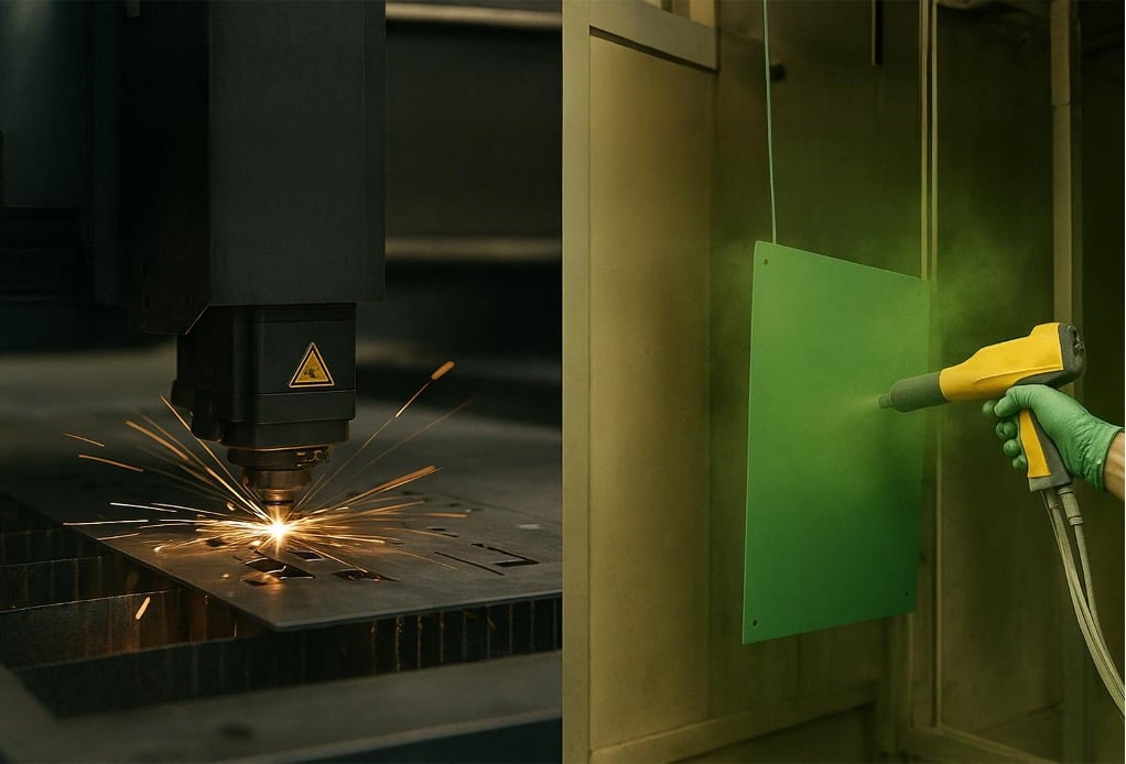
In the world of metal fabrication, two technologies stand out as the pillars of this green revolution: Fiber Laser Cutting and Electrostatic Powder Coating. These processes are not just incrementally better; they are game-changers that systematically attack the two biggest liabilities of old-world manufacturing: energy consumption and waste generation.
At Nova Fabrication, we have built our Engineering philosophy around the principle that a smarter process is a cleaner process. This article will delve deep into the technical and operational specifics of how these two core services are redefining the standards for eco-friendly and cost-effective metal manufacturing.
The Efficiency Revolution in Metal Cutting: The Fiber Laser
The first step in nearly every Steel Fabrication project is cutting raw material. For years, the industry standard was the CO2 laser. Today, it has been almost entirely supplanted by Fiber Laser Cutting, and the primary driver is unparalleled energy efficiency.
1.1. The Energy Drain of Legacy Tech: Why CO2 Lasers Failed the Efficiency Test
To understand why fiber is so revolutionary, we must first look at what it replaced. A CO2 laser creates its beam by exciting CO2 gas molecules with a high-voltage electrical discharge. This process is notoriously inefficient:
- Poor “Wall-Plug” Efficiency: This is the measure of how much electrical power drawn from the wall is actually converted into cutting power. A CO2 laser has a wall-plug efficiency of only 5% to 10%. This means that for every 1000 watts of power it consumes, only 50-100 watts are used for cutting. The other 90-95% is lost as waste heat.
- Massive Cooling Demands: All that waste heat must go somewhere. CO2 lasers require enormous, energy-hungry water chillers running constantly just to keep the machine from overheating. This chiller system often consumes as much power as the laser resonator itself.
- Constant Gas Consumption: The laser requires a constant supply of “laser gases” (CO2, Nitrogen, Helium) to be pumped into the resonator to generate the beam, all of which have their own carbon footprint to produce and transport.
1.2. Fiber Laser: The Green Solution to Sheet Metal Laser Cutting
A Fiber Laser generates its beam differently. It uses banks of solid-state diodes to pump light through fiber-optic cables, where it is amplified and focused. This solid-state design is inherently more efficient.
Unmatched Energy Efficiency:
The wall-plug efficiency of a modern Fiber Laser is between 30% and 50%. This is a monumental leap. A 4kW Fiber Laser can perform the same cutting job as a 6kW CO2 laser while consuming less than one-third of the total electricity. When you factor in the elimination of the high-draw chiller systems and resonator gas consumption, the energy savings are staggering. For a fabrication partner like Nova Fabrication, this translates directly into a lower carbon footprint and reduced operational costs—a saving that is passed on to the client.
Reduced Consumables (A Form of Waste Management):
A Fiber Laser system is solid-state.
- No Laser Gases: It does not consume any gases to generate the beam.
- No Internal Mirrors: CO2 lasers use a complex system of internal mirrors (including expensive optics) to direct the beam, which degrade and must be replaced. A fiber laser delivers the beam through a sealed, maintenance-free fiber optic cable.
- Longer Lifespan: The diodes in a fiber laser source have a typical lifespan of over 100,000 hours, far exceeding the 20,000-hour life of a typical CO2 resonator.
1.3. Waste Management in Cutting: Beyond Energy
The second part of the sustainability equation is waste. In metal cutting, this primarily means scrap metal.
Intelligent Nesting Software:
The most significant waste in laser cutting is the unused portion of the metal sheet—the “skeleton.” Modern CAD/CAM software attacks this problem directly. Our engineers use advanced nesting algorithms to fit parts onto a sheet like a complex puzzle. This software can:
- Share Cut Lines: Two parts can be positioned to share a single cut, completely eliminating the scrap between them.
- Micro-Jigging: Parts are held in place with tiny “micro-jigs” instead of large frames, allowing parts to be nested closer together.
- Remnant Management: The software automatically catalogs any leftover, usable sections of a sheet (remnants) to be used for the next small job, rather than discarding them.
This “virtual” waste management ensures the highest possible material yield, drastically reducing the amount of raw material that needs to be purchased and, subsequently, the amount of scrap that needs to be recycled.
Closed-Loop Recycling:
Of course, some scrap is inevitable. Green fabrication means this scrap is not “waste”—it’s a “by-product.” All scrap skeletons from our Punch Cutting Service and laser cutters are segregated by material (stainless, aluminum, mild steel) and sent for 100% recycling, re-entering the supply chain as raw material.

The Clean Finish: Electrostatic Powder Coating
After fabrication, a product needs a protective and aesthetic finish. This is where the second major pillar of green fabrication comes into play: Powder Coating. It is, without question, one of the most environmentally friendly finishing processes available today, especially when compared to its traditional alternative, solvent-based Wet Painting.
2.1. The Core Problem with Wet Painting: VOCs
Traditional liquid paint is not just pigment; it is pigment suspended in a solvent-based carrier. When the paint is applied, this solvent evaporates into the air to allow the paint to dry. These evaporated solvents are known as Volatile Organic Compounds (VOCs).
- What are VOCs? VOCs are toxic pollutants that contribute to the formation of ground-level ozone (smog), can cause respiratory problems, and are classified as hazardous air pollutants.
- Environmental Control: To (legally) use solvent-based paints, factories must install massive, expensive, and energy-intensive air pollution control systems, such as thermal oxidizers, which literally burn the air to destroy the VOCs.
2.2. Powder Coating’s “Zero VOC” Advantage
Powder coating is a completely dry finishing process. The “paint” is a thermoplastic or thermoset polymer powder. This powder is applied to a grounded metal part using an electrostatic spray gun, which gives the powder particles a positive charge, causing them to cling to the part via static electricity. The part is then cured in an oven, where the powder melts and flows into a smooth, durable, high-quality finish.
The result: Absolutely zero VOCs are released.
This single benefit is a massive environmental victory. It eliminates the primary source of air pollution from the finishing process and removes the need for any energy-consuming pollution control equipment.
2.3. Unmatched Waste Management: The “Reclaim” System
The second major flaw of wet painting is overspray. When spraying a part, a significant amount of liquid paint (often over 50%) misses the target, hits the booth wall, and becomes hazardous, unusable sludge that must be disposed of at great cost.
Powder coating revolutionizes this.
- Overspray is Reusable: The dry powder that does not adhere to the part during the electrostatic application is collected in a “reclaim booth.”
- Closed-Loop System: This overspray is automatically filtered, sieved, and fed back into the main powder hopper to be used again.
- Extreme Transfer Efficiency: With a high-quality reclaim system, it’s possible to achieve material transfer efficiencies of 95% to 98%.
This process nearly eliminates material waste. The tiny fraction of powder that cannot be reclaimed is non-hazardous, solid waste, which is far cheaper and safer to dispose of than toxic paint sludge.
The Synergistic Benefits: How “Green” Processes Create Better Products
The true power of sustainable manufacturing is how these processes work together. The output of one “green” process becomes the perfect input for the next, creating a workflow that is faster, cheaper, and higher quality.
Case Study: A Server Cabinet Manufacturing Project
- Clean Cut, No Prep: A part for an Aluminum Cabinet is cut on the Fiber Laser. Because the cut is so precise and clean (minimal dross/slag), it does not require secondary grinding or chemical cleaning. This saves an entire step that would have consumed energy (for grinding tools) and produced waste (grinding dust or chemical sludge).
- Superior Adhesion: This clean, laser-cut surface is the ideal substrate for powder coating. The powder adheres perfectly without the need for toxic, solvent-based primers.
- Durable, One-Coat Finish: The part is then powder-coated. Unlike wet paint, which often requires a primer coat, a base coat, and a clear coat (three separate application and curing cycles), powder coating achieves its full durability in a single application and cure.
This synergistic workflow—from Sheet Metal Laser Cutting to Press Brake Bending Service to Electrostatic Powder Coating—is not only more environmentally friendly, but it is also faster and produces a more durable final product.
Your Supply Chain, Your Footprint: The Importance of Scope 3 Emissions
Why should a client—a tech company, an architect, or an automotive firm—care about their supplier’s energy efficiency? The answer is Scope 3 Emissions.
- Scope 1: Your company’s direct emissions (e.g., your own factory boilers).
- Scope 2: Your company’s indirect emissions from purchased electricity.
- Scope 3: All other indirect emissions from your entire value chain—this most importantly includes the emissions of your suppliers.
For most modern companies, Scope 3 emissions are the largest part of their carbon footprint. This means your company’s “green” credentials are only as good as the partners you choose.
When you partner with a Contract Metal Manufacturing firm like Nova Fabrication, you are inherently reducing your own Scope 3 emissions. By choosing a supplier that has already invested heavily in Fiber Laser technology and VOC-free Powder Coating, you are making your own end-product more sustainable. This is no longer a “nice-to-have”; it is a competitive advantage and, in many cases, a non-negotiable requirement for bidding on major contracts.
Conclusion: Green Fabrication is Simply Better Fabrication
Sustainable Manufacturing is not a trend; it is the new operational standard. It is the logical and inevitable outcome of a relentless pursuit of efficiency.
Fiber Laser Cutting and Electrostatic Powder Coating are the perfect embodiments of this philosophy. They prove that you do not have to choose between profitability and environmental responsibility.
- Fiber lasers are faster, more precise, and use less energy than their predecessors.
- Powder coating is more durable, higher quality, and produces zero VOCs and near-zero waste compared to liquid paint.
At Nova Fabrication, our entire Metal Manufacturing process is built on this principle. We invest in green technology because it is the most efficient, most reliable, and most cost-effective way to deliver the superior quality our clients demand. Choosing a sustainable partner is no longer a compromise—it’s the smartest business decision you can make.
The Micron-Level Difference: Understanding Tolerances in Gear Grinding
In engineering, “precision” is a relative term. While the tolerances achieved with a standard CNC Milling Service (e.g., +/- 0.05 mm) are sufficient for many applications, in the world of high-performance Gear Fabrication, these tolerances are unacceptably loose. Here, we are talking about precision at the micron level (1 micron = 0.001 mm).
3.1. Gear Quality Standards (DIN and AGMA)
Gear quality is defined by international standards (such as DIN 3961/3962 or AGMA 2000/2015). These standards are based on a series of parameters that measure how much a gear deviates from its theoretical perfection. The quality class is expressed as a number, typically ranging from 1 (highest precision) to 12 (coarsest) in the DIN standard.
A gear produced only by milling or hobbing, without heat treatment, is typically a DIN 7-9 quality. However, the distortions that occur after heat treatment (hardening) can degrade this quality down to a DIN 10-12 level. In contrast, a gearbox that must operate at high speed and with low noise usually requires a quality class between DIN 3 and DIN 5.
The only way to achieve this quality class is through a Grinding Service.
3.2. Critical Geometric Errors Corrected by Grinding
Grinding corrects specific errors that directly impact a gear’s performance:
- Profile Error ($f_{Hα}$): This is the deviation from the ideal curved profile of the tooth, known as the “involute.” This error prevents the gears from “rolling” smoothly against each other and causes noise. Grinding redraws this profile with micron-level accuracy.
- Helix Angle Error ($f_{Hβ}$): In helical gears, this is the deviation of the tooth’s angle from the theoretical helix line. This error causes the load to be unevenly distributed across the tooth face, leading to stress concentration on one edge. Grinding perfects this angle along the entire tooth width.
- Pitch Deviation ($f_p$): This is the inconsistency in the distance between adjacent teeth. During heat treatment, some teeth move closer together while others move farther apart. This creates shock loads and “rattle” during torque transmission. Grinding precisely equalizes the distance between every tooth.

The Role of Material and Its Challenges in the Grinding Process
The complexity of a grinding service stems not only from its geometric precision but also from the properties of the materials it works with.
4.1. Grindability and Material Hardness
High-performance gears must withstand extreme loads and wear. For this reason, they are typically manufactured from alloy steels such as 8620, 4140, 9310, or nitriding steels. During the Gear Fabrication process, these parts undergo heat treatments (usually carburizing or induction hardening) that bring their surface hardness up to 58-64 HRC (Rockwell C).
At this level of hardness, the material can no longer be machined with conventional cutting tools (like milling cutters or lathe tools). The only thing that can shape the material is abrasive grains that are even harder. This is where the Grinding Service comes in.
4.2. The Risk of “Grinding Burn”
Grinding is, in essence, a high-speed friction process that generates an immense amount of heat. The greatest risk in the grinding process is thermal damage known as “grinding burn.” If the process is not properly controlled, the localized temperature increase on the gear’s surface will ruin the material’s microstructure:
- Re-tempering (Softening): If the surface gets too hot, the hardened structure is “tempered” back and becomes soft. This catastrophically reduces the gear’s wear resistance.
- Re-hardening (Cracks): If extreme heat is followed by a sudden quench (by the coolant), an undesirable, highly brittle “martensite” layer forms on the surface. This layer leads to microscopic cracks and can cause the gear to fail catastrophically during operation.
4.3. How to Prevent Grinding Burn (The Secret of a High-Quality Service)
An expert Grinding Service provider, like Nova Fabrication, controls three key variables to manage this risk:
- Correct Wheel Selection: A wheel is chosen that matches not only the material’s hardness but also its “grindability.” Different abrasives like Aluminum Oxide, CBN (Cubic Boron Nitride), and different bond hardnesses are used.
- Precise Feed Rate: The machine is set to remove only a few microns of material at a time. These “spark-out” passes minimize heat generation.
- Coolant Management: The role of the coolant is not just to cool. It also cleans metal chips (swarf) from the wheel’s pores with high pressure, keeping the wheel “sharp.” A clogged wheel will “rub” instead of “cut,” causing an immediate burn.
Beyond the Teeth: The Importance of All Gear Surfaces
The secret to a high-performance gear does not lie only in its perfect tooth profiles. All other critical surfaces of the gear, such as those that sit on the shaft or in a bearing, must also have the same micron-level precision. Otherwise, even perfect gears will be misaligned and fail.
5.1. ID/OD Cylindrical Grinding
A gear’s performance depends on how concentric its tooth profile (pitch circle) is with the central axis of the bore.
- First Step (Turning): The part is first machined on a Cnc Turning Service. At this stage, a small amount of “stock” is left on for heat treatment and grinding.
- Heat Treatment: As the part hardens, the inner bore (ID) and outer diameters (OD) also distort.
- Final Step (Grinding): The Grinding Service then grinds the gear’s inner bore (ID) and, if applicable, its shaft diameter (OD). This process ensures the gear fits onto its bearings or shaft with zero play (zero runout). If there is an eccentricity error between the bore and the tooth profile, the gear will “wobble” as it rotates, causing vibration throughout the entire system.
5.2. Surface Grinding
Helical gears, in particular, create an axial “thrust” force as they rotate. This force is countered by the gear’s side faces.
- Surface Grinding ensures that these side faces (faces) are perfectly flat and perfectly perpendicular to the axis of the bore.
- If these faces are not properly ground, the gear will “wobble” laterally as it rotates, which applies an uneven load to the bearings and other components.