
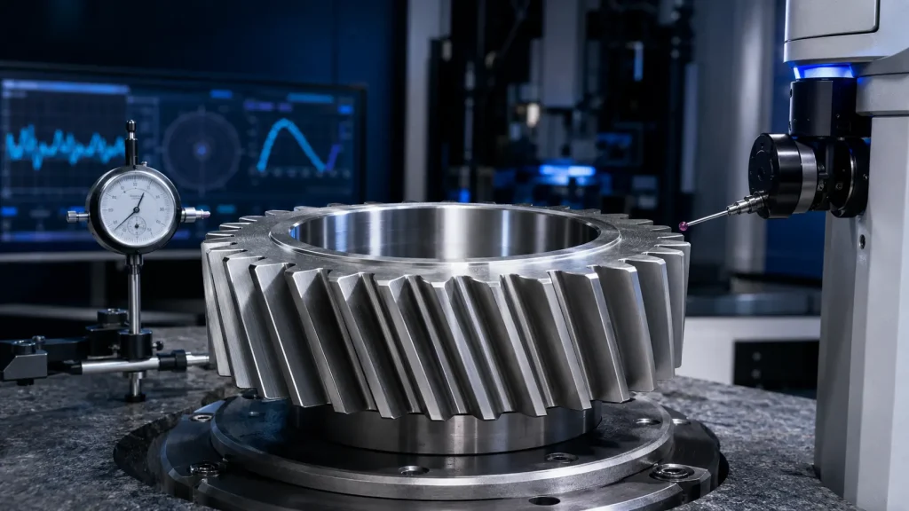
A gear can look clean, measure correctly across its outside diameter and still create noise, heat, vibration or positioning error in service. The reason is simple: gear quality is not one dimension. It is a combination of tooth geometry, concentricity, mating clearance, surface condition and the way the gear behaves when it rolls with another member.
For buyers sourcing custom gear fabrication, inspection should therefore begin with the application and drawing—not with a generic request for a “high-precision gear.” Backlash, runout, tooth profile and surface finish answer different questions. Each needs a defined datum, method and acceptance limit if the inspection report is to provide useful evidence.
Start with an Inspection Plan, Not an Instrument
The correct inspection scope depends on gear type, module or diametral pitch, tooth count, pressure angle, helix angle, face width, material, heat treatment and required quality class. The drawing should also identify the functional datum—often a bore, journal or mounting face—because a precise tooth form can still run eccentrically if it is evaluated from the wrong reference.
Operating information matters too. A positioning gearbox may be highly sensitive to lost motion, while a high-speed drive may prioritise transmission error, noise and surface waviness. A heavily loaded gear may need particular attention to contact pattern, hardness and finishing. Early engineering support helps connect these service conditions to a manufacturable drawing and a proportionate inspection plan.
What the Four Main Checks Tell You
Characteristic | What it describes | Common inspection approach | Risk if uncontrolled |
Backlash | Clearance between mating flanks when direction reverses | Controlled pair check; tooth-thickness measurements | Binding or heat if low; lost motion or impact if high |
Runout | Eccentricity of tooth geometry relative to the datum axis | Ball/pin or probe check; double-flank rolling | Cyclic load, vibration, noise and changing backlash |
Tooth profile | Deviation of the actual flank from its specified involute or modification | Analytical gear measuring system or agreed scanning method | Poor contact, transmission error, noise and local stress |
Surface finish | Roughness, waviness and texture of the working flank | Stylus profilometer or agreed optical method | Film disruption, friction, wear, scuffing or noise |
1. Backlash: Clearance in the Mating Gear Pair
Backlash is the available clearance between the non-working flanks of mating teeth. It becomes visible as rotational movement when one gear is held and the other is gently rocked from one flank to the opposite flank. This clearance allows for lubricant, manufacturing variation, elastic deflection and thermal expansion. Zero backlash is therefore not automatically the best target.
Too little backlash can make the mesh sensitive to centre-distance error, shaft deflection, contamination or temperature change. The result may be binding, heat, noise and accelerated damage. Too much backlash creates lost motion, tooth impact during reversal and poor positioning. The correct range follows the gear system, load, speed, lubrication, temperature and required motion accuracy.
Backlash is not solely a property of one loose gear. Tooth thickness, mating-gear geometry, centre distance, alignment and mounting accuracy all affect the result. Manufacturers commonly control tooth thickness by span measurement, measurement over pins or balls, or other drawing-specified methods. These checks help predict mesh clearance, but an assembly or controlled-pair check is the clearest way to confirm actual backlash under defined conditions.
A useful backlash requirement states the measurement location, operating or test centre distance, temperature, applied measuring load and whether the production gear is paired with its actual mate or a calibrated master. Without these details, two inspectors can obtain different values from the same components and both may believe their result is correct.
2. Runout: Is the Tooth System Concentric with the Datum?
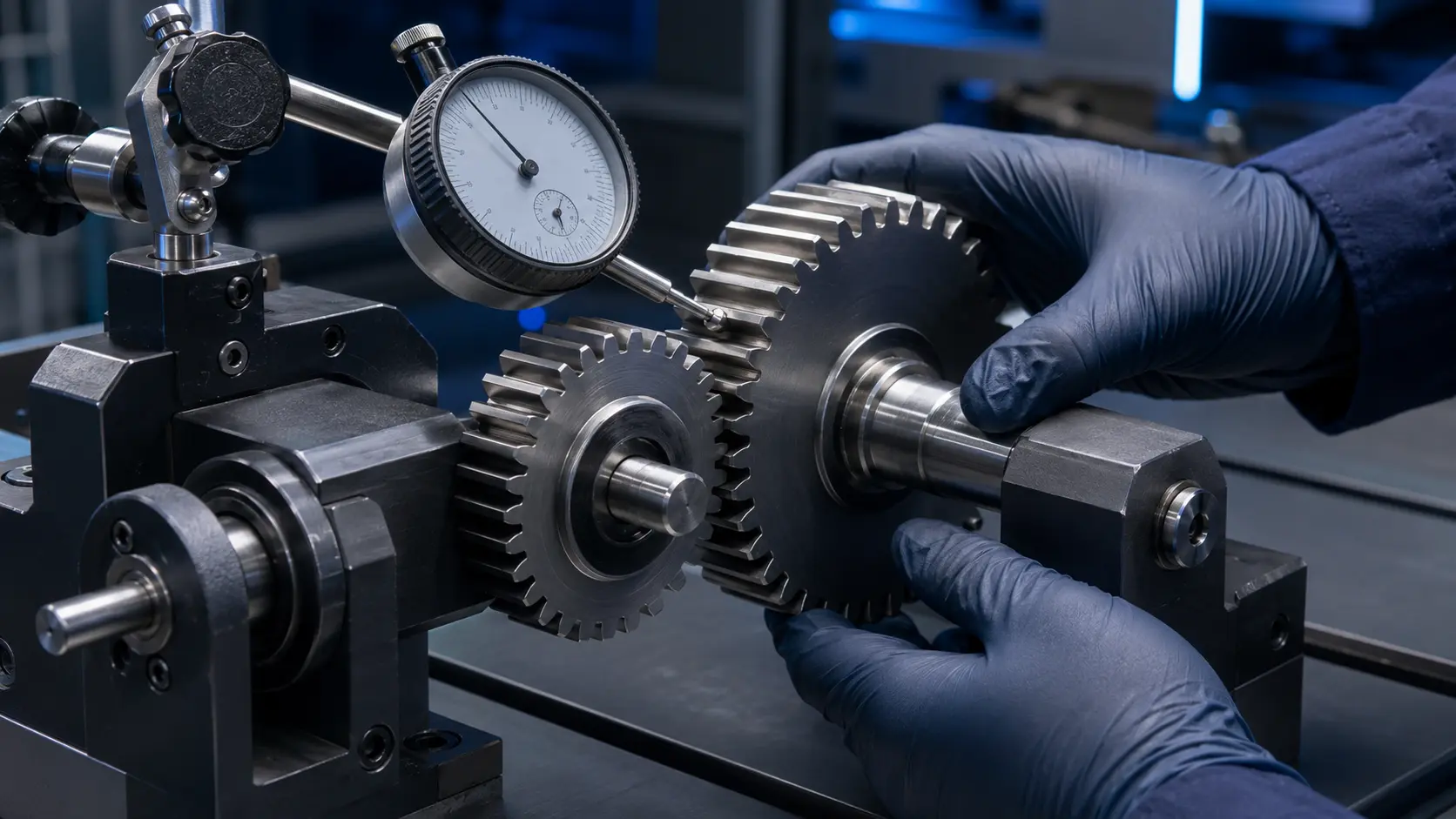
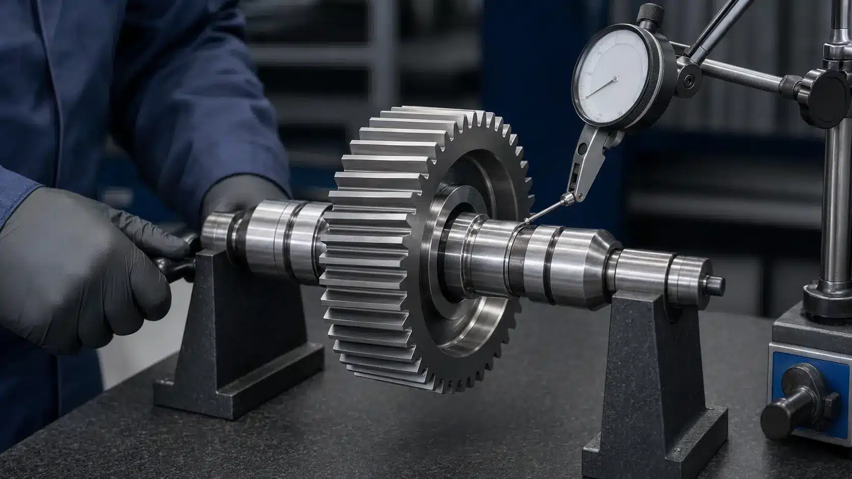
Gear runout describes eccentricity of the tooth system relative to the selected rotation axis. A common radial check places a suitable ball, pin or probe in successive tooth spaces while the gear is indexed around its datum. The total indicator change reveals how the tooth geometry moves toward and away from the axis over one revolution. The contact element and datum setup must suit the gear geometry and the specified standard.
Runout can originate in the blank, bore or journal, workholding, gear-cutting setup, heat-treatment distortion or a finishing operation referenced from a different datum. Its effect is cyclical: tooth loading and effective backlash can rise and fall once per revolution, producing vibration, noise and uneven contact. A face-wobble or axial runout check answers a related mounting question, but it should not be confused with radial tooth-system runout.
Double-flank rolling is another useful functional method. A product gear is rolled in close mesh with a master while centre-distance variation is recorded. The result can reveal radial composite deviation, functional runout, tooth-to-tooth variation and local damage such as nicks. Because the test uses a controlled tight mesh, it does not by itself reproduce the operating backlash of the final gearbox.
Good datum strategy starts before tooth cutting. Bore, locating faces and gear features should be produced and inspected through a coherent route using suitable machining services. Re-clamping a nearly finished gear from a non-functional surface can convert small setup error into visible tooth runout.
3. Tooth Profile: Does the Flank Match the Intended Geometry?
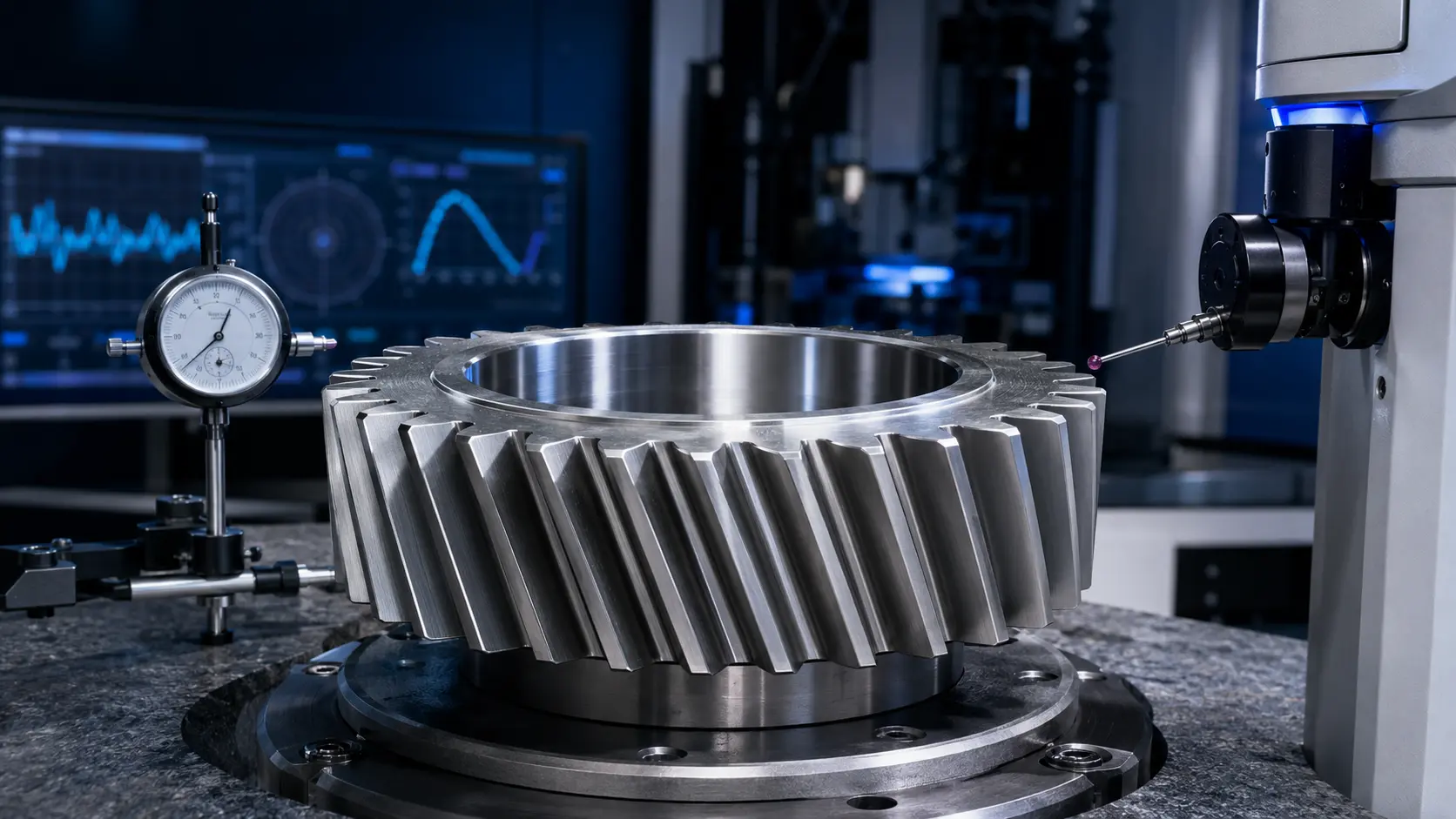
For most cylindrical gears, the working flank is based on an involute profile. A gear measuring system traces the flank through a defined evaluation range and compares the measured geometry with the nominal profile. Reports may separate total profile deviation, profile-slope deviation and profile-form deviation in the terminology of the selected standard. The result is normally shown as both values and traces, because the shape of the deviation helps identify the cause.
The nominal target may intentionally include tip relief, root relief or another microgeometry modification. An inspection program must evaluate the designed shape rather than treating every departure from a pure involute as an error. This is why the released drawing, modification chart and data revision must match the inspection program.
Tooth profile is only one part of flank geometry. Helix or lead inspection checks the tooth direction across the face width; pitch inspection checks tooth spacing around the circumference. A gear can pass profile but fail lead or pitch, so the required quality class should identify the relevant characteristics rather than asking for a vague “profile certificate.”
Process choice influences the error pattern. Hobbing, shaping, form milling, five-axis machining and hard finishing each have different capabilities and control needs. Nova’s overview of gear manufacturing explains how design, material selection, machining and quality control form one connected production route; its CNC milling service provides further context for controlled machining operations.
4. Surface Finish: What Condition Is the Working Flank In?
Surface finish describes more than whether a tooth looks shiny. The working flank contains short-wavelength roughness, longer-wavelength waviness and a directional texture created by cutting, grinding, honing or polishing. These features can affect lubricant-film formation, friction, running-in behaviour, scuffing risk, contact fatigue and audible noise, although their importance varies with load, speed, lubrication and material.
Ra is widely used, but one average roughness value may not describe isolated peaks, valleys or periodic waviness. A specification may instead or additionally require Rz, Rq or other parameters. It should also define the governing surface-texture standard, filter or cut-off, evaluation length, measuring direction and flank location. Results obtained across the machining lay may not match results taken along it.
A contact stylus profilometer is common; agreed optical methods may be appropriate for certain sizes, finishes or access conditions. Visual inspection remains useful for grinding burn, scratches, pitting, nicks or handling damage, but appearance cannot replace a quantified texture measurement. Hardness and metallurgical checks may also be needed when heat treatment or grinding integrity is critical.
Finishing operations should be chosen around function and stock allowance. Nova’s grinding service describes grinding as a route to tighter dimensional accuracy and lower surface roughness, while its article on micron-level grinding for gear fabrication provides related detail on critical finished surfaces.
How the Main Inspection Methods Complement One Another
Analytical gear measurement isolates characteristics such as profile, helix and pitch and is valuable for diagnosis and conformity to a flank-tolerance system. Single-flank rolling evaluates rotational or transmission error while two gears roll together under controlled backlash. Double-flank rolling records radial movement in a forced mesh and is effective for composite deviation, functional runout and local tooth defects. Conventional gauges and CMM inspection remain useful for bores, faces, diameters, tooth thickness and general geometry.
The appropriate combination depends on risk. A prototype positioning gear may need detailed analytical traces and actual-pair backlash. A stable production gear may use periodic analytical verification supported by faster functional screening. A safety- or performance-critical project may require full traceability and customer-defined sampling. The inspection plan should state which method is for acceptance and which is for process monitoring.
What Buyers Should Expect in a Gear Inspection Report
A useful report connects every result to the part that was measured and the method used. At minimum, buyers should expect the part number, drawing revision, batch or serial identification, material or heat-treatment reference, inspection date and the applicable standard or quality class. The report should identify the datum, setup, instrument, relevant calibration status and environmental conditions where they materially affect the measurement.
- For backlash: the pair or master, centre distance, measuring load, temperature, location and actual minimum/maximum result.
- For runout: the datum axis, contact element or functional test method, measurement positions and total indicated or composite result.
- For profile: evaluation range, tooth/flank locations, modification target, values, traces and the applicable tolerance class.
- For surface finish: parameter, filter or cut-off, evaluation length, direction, flank location and individual results—not only a rounded average.
A pass/fail stamp without the underlying values is difficult to audit. For custom work, the Inspection and Test Plan should also connect incoming material, in-process checks, heat treatment, final inspection and release documentation. Nova describes its use of project-specific ITPs and quality files on the Why Choose Nova Fabrication page.
Gear Inspection RFQ Checklist
The most effective way to avoid inspection disputes is to define the evidence at the quotation stage. Include the following information with the model and drawing:
- gear type, module or diametral pitch, tooth count, pressure angle, helix angle, face width and all intentional flank modifications;
- material grade, blank condition, heat treatment, hardness range, case-depth or metallurgical requirements, coating and finishing route;
- functional datums, bore and face requirements, permitted runout and the standard or quality grade governing tooth geometry;
- backlash range together with test centre distance, temperature, measuring load, rotation direction and actual mate or master-gear requirement;
- surface-texture parameter, numerical limit, filter or cut-off, evaluation length, measurement direction and required flank locations;
- first-article, sampling or 100% inspection scope; required analytical traces, rolling-test charts, certificates and traceability;
- operating torque, speed, duty cycle, lubrication, noise or positioning target, expected temperature range and any critical failure mode;
Frequently Asked Questions
Is zero backlash always better?
No. A controlled amount of backlash is normally required for lubrication, manufacturing variation, deflection and thermal expansion. Very low backlash can be appropriate in a specialised system, but it must be engineered with the whole gearbox, bearings, centre distance and operating temperature in mind.
Can runout be corrected during assembly?
Some error caused by dirt, poor seating or adjustable mounting may be corrected, but eccentricity manufactured into the tooth system relative to the bore or journal usually requires process correction. The inspection setup should reproduce the functional datum so the source of the error is clear.
Does a smooth-looking gear meet the surface-finish requirement?
Not necessarily. Lighting and polishing can hide texture that a profilometer will detect, while a visually dull surface may still meet its specified parameter. Conformity requires the agreed numerical parameter and method, supplemented by visual checks for damage.
Is a CMM enough for complete gear inspection?
A capable CMM can inspect many blank, bore, face and tooth features when the method is validated. Specialised gear metrology or rolling tests may still be more suitable for analytical flank traces, composite behaviour, production speed or the specified quality system. The instrument should follow the characteristic and risk.
Define the Evidence Before Production Starts
Reliable gear inspection is a chain of evidence. Backlash confirms clearance in the specified mesh; runout connects the teeth to the rotation datum; profile inspection evaluates the intended flank geometry; and surface-texture measurement describes the condition of the working surface. When the drawing, inspection plan and production route use the same definitions, buyers receive results they can compare and manufacturers receive a clear acceptance target.
Nova Fabrication can review gear geometry, machining route, related finishing and project documentation against the application requirements. To confirm feasibility, available inspection scope, quantities and reporting needs, request a project quote with the latest drawing, 3D model and required standards.