
During a bend, the outside of the curve—the extrados—is pulled in tension and tends to lengthen and thin. The inside of the curve—the intrados—is compressed and tends to shorten, which can make the wall buckle into wrinkles. At the same time, radial forces push the circular section toward an oval or flattened shape. The neutral region between the inner and outer surfaces changes less in length, but its position can shift as the forming conditions change.
Two ratios help describe bending difficulty. The diameter-to-wall ratio, D/t, indicates how thin the wall is relative to the tube outside diameter. The centreline-radius ratio, CLR/D, describes how tight the bend is. A larger D/t and a smaller CLR/D generally demand more internal support and tighter process control. They are useful screening tools, but they do not replace trials because material strength, elongation, weld seam, surface condition and batch variation also influence the result.
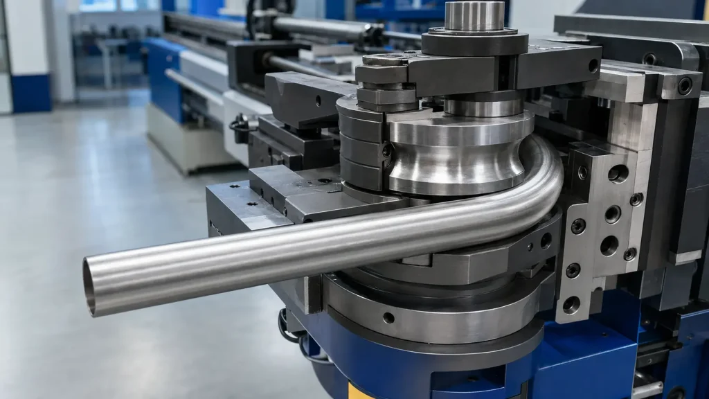
Rotary draw bending is often selected for controlled, repeatable bends and can use a mandrel and wiper die. Other metal bending methods may be appropriate for larger radii, thicker walls or less demanding geometry. The method should follow the part requirement, not the other way around.
Quick Comparison of the Three Main Defects
| Defect | Typical location or sign | Common drivers | Primary controls |
| Wrinkling | Waves or folds on the intrados | Compression instability, thin wall, tight radius, setup error | Wiper and mandrel setup, pressure, boost, lubrication |
| Ovality | Round section becomes oval or flattened | Radial collapse, insufficient internal support | Mandrel type/position, radius, tooling fit, material control |
| Wall thinning | Reduced wall at the extrados | Tensile stretching, tight radius, friction or feed imbalance | Starting wall, CLR, boost, lubrication, controlled draw |
1. Wrinkling on the Inside Radius
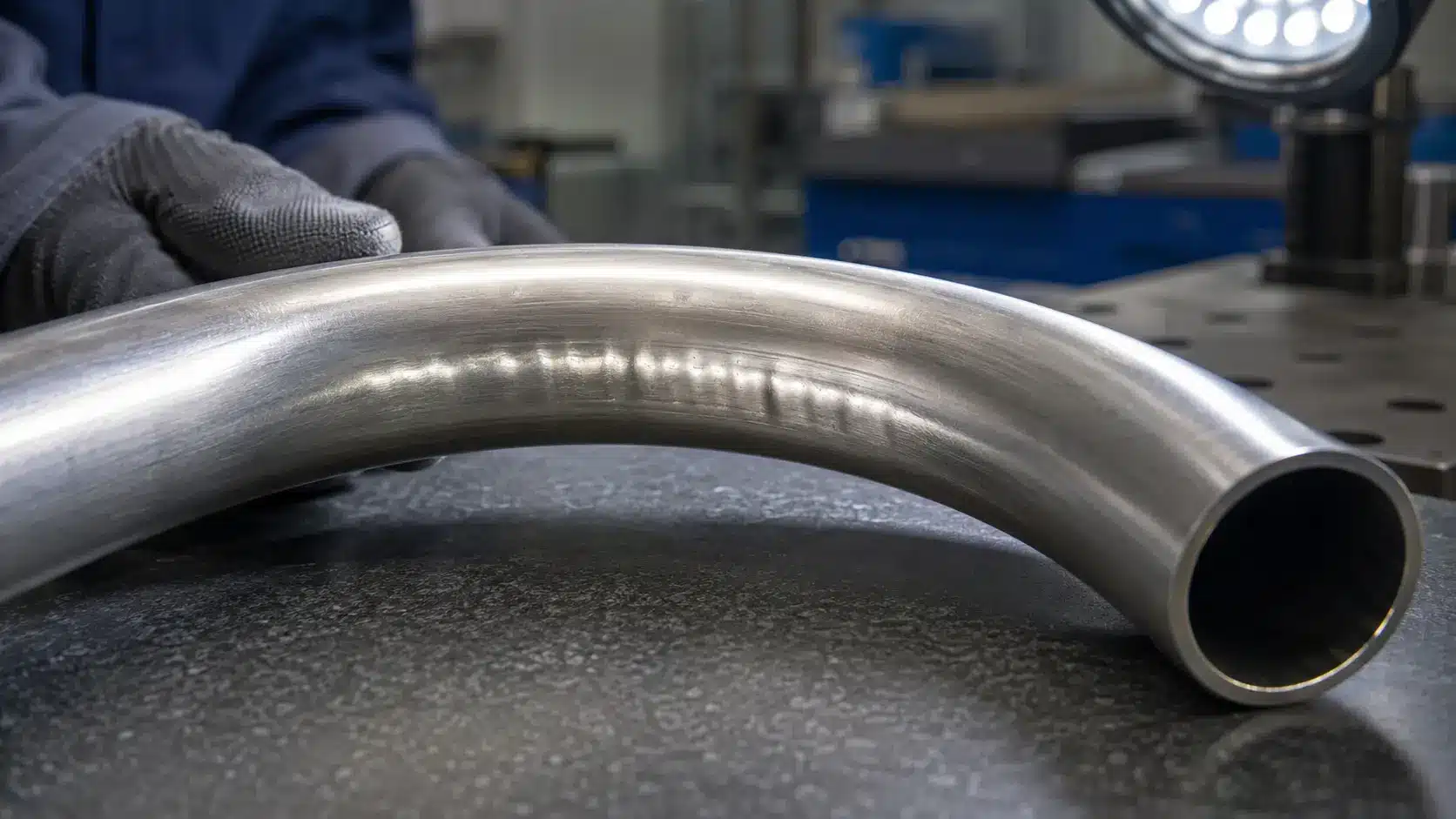
Wrinkling occurs when the compressed inner wall cannot remain stable as material moves around the bend die. It can appear as fine ripples, a repeated wave pattern or a pronounced fold. Even when a wrinkle looks cosmetic, it can reduce internal clearance, create stress concentration, disturb flow and prevent a tube from fitting into a clamp, sleeve or mating assembly.
Typical causes include a high D/t ratio, a tight centreline radius, insufficient pressure-die support, clamp slip, poor lubrication or an incorrectly positioned mandrel. On demanding rotary draw bends, the wiper die is especially important: its tip supports the inner wall near the tangent as compressive stress develops. A worn, mismatched or poorly positioned wiper can allow the wall to buckle before the bend is fully formed.
Prevention is a setup exercise rather than a single machine adjustment. Tooling must match the actual outside diameter and wall thickness; the mandrel should support the section without excessive drag; the pressure die should maintain contact; and any boost should be coordinated with draw speed. If the geometry is still unstable, increasing CLR, selecting a more formable tube condition or increasing wall thickness may be more robust than repeatedly tuning a marginal process.
2. Ovality and Cross-Section Flattening
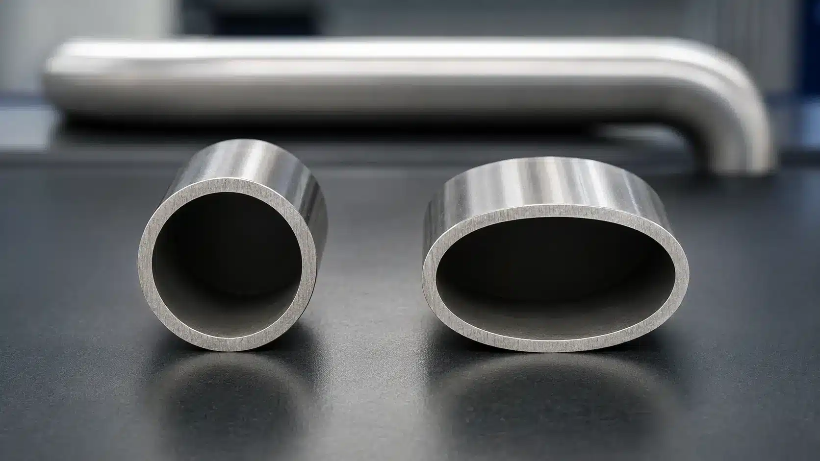
Ovality is the loss of roundness that occurs when the tube’s cross-section flattens during bending. It is commonly checked at the bend apex by measuring the largest and smallest outside diameters. One widely used engineering expression is: Ovality (%) = 100 × (Dmax − Dmin) / Dnom. A buyer specification may use a different denominator, measurement location or limit, so the formula and method should be agreed before inspection.
Some ovality is a natural consequence of bending, but excess distortion can reduce flow area, affect pressure-drop assumptions, weaken a sealed or clamped connection and create visible mismatch in architectural or furniture parts. Tight CLR, thin walls, high material strength, inconsistent tube dimensions and insufficient mandrel support all increase the risk. Square and rectangular profiles show related distortion as side-wall concavity, bulging or corner shift.
A correctly selected plug or ball mandrel supports the tube internally while it passes the tangent. Mandrel position matters: too far back may leave the section unsupported, while an over-advanced or poorly lubricated mandrel can increase drag and leave marks. The bend die groove, clamp and pressure die must also fit the stock. When a project combines bending with profile and pipe laser cutting, holes and slots close to the bend should be reviewed because local openings can reduce section stability or distort during forming.
3. Wall Thinning at the Outside Radius
Wall thinning develops mainly at the extrados, where the material stretches. A common reporting expression is: Wall thinning (%) = 100 × (t0 − tmin) / t0, where t0 is the agreed starting thickness and tmin is the minimum measured wall in the bend. The inspection plan should state whether t0 comes from nominal thickness, an actual pre-bend measurement or a batch value, and where tmin will be measured.
The risk rises as the bend becomes tighter, the starting wall becomes thinner or the material has less useful elongation. Excessive drag, insufficient pressure-die assistance, an incorrect mandrel position or an unbalanced boost setting can increase stretching. Material temper and weld seam behaviour also matter. For example, a nominally identical stainless tube may bend differently when strength, surface finish or dimensional variation changes between supply batches.
The most reliable controls are often designed in: choose a practical CLR, allow adequate starting wall thickness and specify a tube grade and condition suited to forming. During production, tooling alignment, lubrication, draw speed and pressure-die or carriage boost are tuned together. Projects using stainless steel fabrication should also protect the finished surface from contamination and tool marking while maintaining the lubrication needed for a stable bend.
Other Defects That Often Appear with the Main Three
Tube bending problems rarely occur in isolation. Cracking or splitting may appear at the extrados when tensile strain exceeds the material’s forming capacity. Springback can leave an incorrect angle or rotation after the tooling opens. Collapse is a severe form of section distortion, while twisting can move a profile or a sequence of bends out of plane. Welded tube may show seam-related marks or inconsistent deformation if seam quality and orientation are not controlled.
Tool marks, scratches and lubricant residue may also be unacceptable on visible or hygienic parts even when the geometry passes. That is why the drawing should separate functional limits—such as minimum wall or maximum ovality—from cosmetic requirements such as allowable witness marks, polishing direction and protected surfaces.
How Tooling Controls the Bend
In rotary draw bending, the bend die establishes the centreline radius, and the clamp die grips the tube so it can be drawn around that form. The pressure die supports the straight section at the tangent and can assist material flow. A mandrel supports the tube internally to limit collapse and ovality; ball mandrels provide more support through demanding bends than a simple plug. The wiper die supports the compressed inner wall and helps suppress wrinkles.
These tools work as a system. More pressure is not automatically better: excess force or an over-tight tool can increase friction, leave surface damage or shift the defect elsewhere. Lubrication must suit the tube and tooling materials, the required finish and any downstream cleaning or welding. Production stability also depends on tool condition; worn grooves, damaged tips and inconsistent setup can turn a previously capable bend into a recurring quality problem.
DFM and RFQ Information That Reduces Risk
Early engineering support can identify an impractical radius, a feature placed too close to the tangent or an inspection requirement that cannot be measured on the finished part. A useful tube-bending RFQ should include:
- tube outside dimensions, wall thickness, material grade, temper or condition, and whether the stock is seamless or welded;
- centreline radius, bend angle, bend direction, straight tangents and 3D rotations;
- dimensional tolerances plus separate limits for ovality, minimum wall, wrinkles, collapse and surface marks;
- weld seam orientation, grain or extrusion considerations, and protected cosmetic surfaces where relevant;
- holes, slots, end forms, weld preparations and other features located near bends;
- quantity, prototype or first-article needs, finish, cleaning, traceability and inspection documentation.
For assemblies that also require cutting, welding, machining or finishing, a review through fabrication and engineering helps establish the correct operation sequence. The bend may need to occur before laser-cut features, or a cut feature may be useful for orientation. The best route depends on tolerances, access, tooling clearance and production volume.
Inspection: Define the Method as Well as the Limit
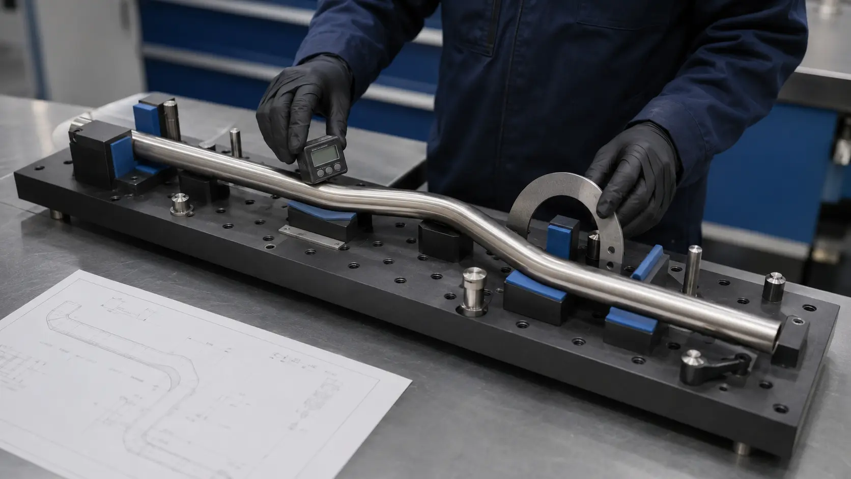
Visual inspection is useful for wrinkles, cracks, scratches and obvious collapse, but it cannot quantify every risk. Bend angle, radius, tangent location and overall geometry may be checked with fixtures, templates, gauges or coordinate measurement. Ovality requires Dmax and Dmin measurements at defined locations and orientations. Wall thickness may be checked with suitable ultrasonic equipment, mechanical methods or destructive sectioning during process qualification, depending on tube size, material, access and the required confidence.
Acceptance language should be measurable. “No wrinkles” may be appropriate for a visible surface, but a fluid or fatigue-critical part may also need quantified minimum wall, ovality and dimensional requirements. Conversely, a decorative frame may prioritise appearance over internal geometry. The governing drawing, customer specification, industry code and service conditions determine what is acceptable; there is no single universal percentage for every tube bend.
A first article or bend trial is valuable when the combination of D/t, CLR/D, material and finish is new. The approved sample can establish the setup and inspection baseline before volume production within a broader custom metal manufacturing programme.
Frequently Asked Questions
Does mandrel bending eliminate every defect?
No. A mandrel improves internal support, but its type, clearance, position and lubrication must be correct. Wrinkle control may still require a wiper die and balanced pressure or boost, while material variation can still affect thinning and springback.
What is an acceptable ovality percentage?
It depends on the application, tube specification and governing code. A limit suitable for a furniture frame may be unsuitable for a pressure, sealing or high-cycle fatigue application. State the calculation method, measurement location and allowable value on the drawing or quality plan.
Can welded tube be bent successfully?
Yes, provided the material, dimensional consistency, seam integrity and seam orientation are compatible with the bend. The preferred orientation can depend on the process and part, so it should be qualified rather than assumed.
Can wrinkles be repaired after bending?
Minor cosmetic irregularities may sometimes be addressed, but forcing or grinding a wrinkle can damage the wall and does not restore controlled geometry. Functional wrinkles should normally be prevented through design and setup; any repair method must be approved for the application.
Plan the Bend Around Its Function
A high-quality tube bend is not defined only by angle. It must preserve enough wall, section shape, alignment and surface quality for the part’s real service. Clear drawings, realistic geometry and agreed inspection methods give the manufacturer a stable target and give the buyer objective evidence of conformity.
Nova Fabrication can review tube geometry, related fabrication operations and project-specific quality expectations. To discuss feasibility, quantities and documentation, request a project quote with the drawing, material specification and required acceptance criteria.